About Triangle Meshes
Mesh Editor operates on triangle meshes, which consist of three types of elements: vertices, edges, and triangles.
-
Vertices are points in 3D space. We can also associate other information with vertices -- for example, color.
-
Edges are connections between pairs of vertices.
-
Triangles are triples of vertices.
Explain the benefits you offer.
Don't write about products or services here, write about solutions.
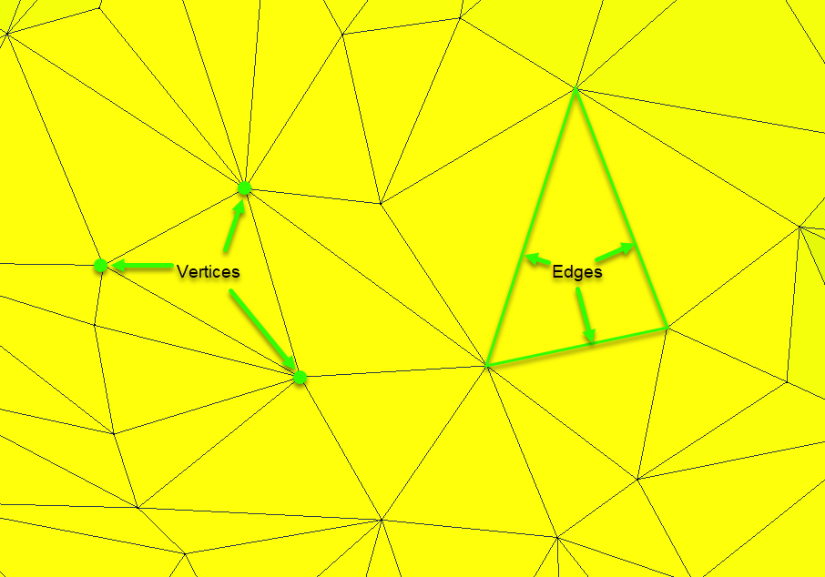
In Mesh Editor we also use the term faces to refer to triangles (though really triangles are only one type of face). Edges connect the corners of triangles, and vertices are points where two or more edges meet (corners of the triangles).
We use the term neighbours to refer to two triangles that share an edge, two edges that share a vertex, or two vertices that share an edge. We use the term incident to refer to an element that is part of another. For example, an edge is "incident upon" one or more triangles.
A mesh boundary is one or more edges incident upon only one triangle. A mesh is called open if it has one or more boundaries, and closed if it has no boundary edges.
A shell is a connected set of triangles. In other words, starting from one triangle, you can walk to any other triangle in the shell without leaving the surface. This is also sometimes referred to as a connected component.
Surface normal and tangent: you can think of a tangent plane at a point on the surface as the plane that is parallel to the surface at that point. The normal vector at a point is the vector that is perpendicular to this tangent plane. You can think of the normal vector as the vector that points "straight out" of the surface, and the tangent as the plane that fits "along" the surface at a given point.

UVs/Texture coordinates: UV mapping associates a 2D coordinate with each vertex in the mesh. This allows for texture mapping, which "wraps" a 2D image onto a 3D surface. The texture coordinates or UVs are the set of 2D coordinates for all triangle vertices.
Manifold vs. non-manifold: A manifold surface has either one or two triangles neighbouring every edge in the mesh. A non-manifold surface can have three or more triangles on a single edge. Usually there are only a small number of non-manifold edges in a non-manifold mesh. See the Generate Complex Tool topic for more details.
About Face Groups
Mesh Editor allows you to assign a tag to any triangle in the mesh. These tags are represented by colors in the application. A set of triangles with the same color tag is called a face group.
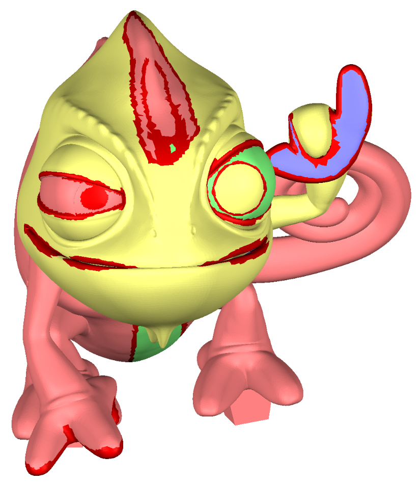
A Gecko with many face groups
Note: To see face groups, you must choose Group Color (Default) in Mesh Color Mode in the preferences window.
To assign a set of triangles to a new Face Group, select them using the Select tool, then on the Select panel, click Modify > Create FaceGroup. To remove the Face Group identifier from a set of triangles, select the triangles and click Modify > Clear FaceGroup.
Once you have one or more Face Groups you can do things with them. In Select mode, double-click inside a group to select the entire group. Some tools are also aware of Face Groups. For example, in the Remesh tool, you can check the option Preserve Group Borders  .
.
This will preserve the shape of the Face Group, even if we add or remove triangles. In the following example, notice that the outline of the green face group remains the same, even as many triangles are added inside and outside of the group.
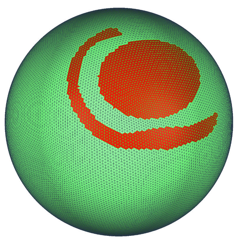
Before remeshing
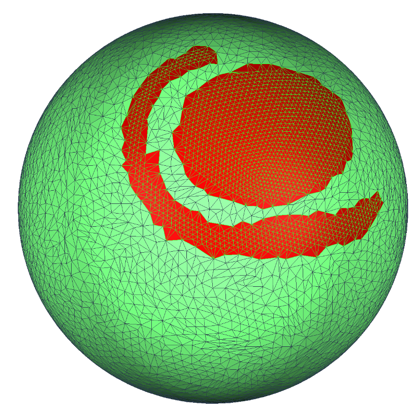
After remeshing
The Stamp tool creates shapes in the mesh by refining the mesh (inserting vertices, edges, and triangles), and assigning triangles to Face Groups.
Import/Export
There are three ways to Import a mesh file into MeshEditor:
- Import button on the splash screen, when you start the app
- Import button at the top of the left sidebar
- Import button in the File menu
MeshEditor also comes with three default objects (Bunny, Sphere, and Plane), which are available in the startup splash screen and also the File menu.
If the scene is not empty, then when you Import you will be asked if you want to Append the imported objects to the existing scene, or Replace the current scene with a new scene entirely.
You can Export from the left sidebar and also the File menu, or use the Ctrl/Cmd+e shortcut. In this case you will be presented with a file dialog where you can select the desired output mesh file path and also the mesh format.
Finally, there is the Import Reference option. This is just like Import, except that Reference objects cannot be modified.
Open/Save .cos format
In addition to Import/Export, the File menu also has Open, Save, and Save As options (you can also Open from the startup splash screen). These are for working with the native MeshEditor .cos file format. This is a binary format that no other software can read or write. It allows us to store things that the various mesh formats do not support; .cos files also open and save much more quickly than we can import or export meshes.
if you are working on a project, we strongly recommend you use a .cos file. You can quickly (and frequently!) save using the Ctrl/Cmd+s hotkey, just like any other program.
One caveat with .cos files is that we do sometimes break backwards-compatibility. Your old .cos files will always open fine in the newest versions of Meshmixer, but new .cos files might not open in old versions. For example, in MeshEditor 3.0 we had to make breaking changes, so 3.0+ files do not load in the 2.X versions.
Import Formats
File formats that can be imported into MeshEditor.
STL
The canonical 3D printing format. Unfortunately this is also just about the worst way to store a mesh! See below under the Preferences section for details. We support both ASCII and Binary STL. For Binary STL, we support face colors, but only one of the modes (there are two conventions and there is no way to tell which is which!). And we bake these face colors into vertex colors, so there is some blurring.
OBJ
The Wavefront OBJ format is widely used in many industries, and this is the format we have the most extensive support for. OBJ can store arbitrary polygons, but we always convert to triangles on input. We support the color-per-vertex extension used by some other software (eg ZBrush). OBJ is also (currently) the only format where we support importing texture maps (only diffuse maps). We really prefer the texture images to be PNG or JPG formats. For more info on how we handle groups in OBJ files, see the details below in the Preferences section.
AMF
Additive Manufacturing Format (AMF) is a relatively new format that was designed to replace STL for 3D printing. Frankly we still think this format is not as good as OBJ, but that's just our opinion. We only support a subset of the expansive AMF format, in fact we only support the triangle-mesh portion.
PLY
Polygon File Format PLY is a format produced by many 3D scanners. We support ASCII and Binary PLY, and we can read per-vertex colors in PLY files. Note that PLY is quite a tricky format, so if you have a PLY file that gives you an error, please send it to us and we can probably help.
OFF
OFF format is a very basic format that stores a list of triangles, essentially a very simple version of OBJ. You might run across OFF files in some old 3D file databases.
3MF
Meshmixer support for the 3MF format is relatively new, so there may still be bugs or other issues. This format supports vertex colors and texture/material information.
COS
In addition to being able to Open a .cos file (which replaces the current scene), you can Import a .cos, to append the objects to the current scene.
Note:
Note that for all these formats, we discard the normals stored in the files. We always re-estimate our own normals from the mesh triangles. Also, most of these formats don't tell us what units they were saved in!! So for formats that don't (everything except DAE and AMF), we assume millimeters.
Export Formats
File formats that can be exported from MeshEditor.
STL
MeshEditor can export both ASCII and Binary STL. No colors, though.
OBJ
We export OBJ, and optionally also OBJ with the color-per-vertex extension. In addition, if your model has texture maps, we will export those too. Note, however, that our image file-naming is a bit buggy, so if you are going to export an OBJ with textures, we strongly recommend you do it in a different folder than your source files!
DAE
This is the COLLADA format , which MeshEditor currently can only write. We simply write out the meshes, not any of the other things you might find in a Collada file (cameras, etc).
PLY
We write ASCII PLY files with RGBA colors.
AMF
Similar to DAE, our AMFs just contain the mesh data, nothing else.
WRL
We write Version 2.0 utf8 WRL/VRML files, with per-vertex colors. You might need these for some 3D printing services. We don't support UV-mapped textures in WRL (yet).
SMESH
This is a pretty obscure format that is used in finite-element simulation, it is basically a concatenated .ele and .node file (if that means anything to you!).
3MF
Exporting in 3MF format will export the mesh, vertex colors, UVs, and texture files.
Up Direction
Choose which axis points up.
One complication with many of the common 3D mesh formats is that they do not store which direction is "up" in the model. Unfortunately different 3D programs are roughly 50-50 split between "Y-up" and "Z-up". If you are using 3D printing software, you are mostly dealing with Z-up, while if you are using film & games software, or Autodesk Fusion 360, chances are you have files that are Y-up. This is a nightmare!
Inside MeshEditor, we use Z-up. This decision was made years ago and changing it now would be a huge amount of work. However, since many files are Y-up, we provide an option to automatically handle the Z/Y-up conversion on import and export. This option is available in two places: in theFile menu > Preferences dialog under the File tab, and also in the Append/Replace dialog. The setting is called Flip Z-Y axis on Import-Export, as shown below.
Import/Export Preferences
File settings related to import and export actions.
OBJ options
There are a few options for the OBJ file format. If you un-check Load Materials and Textures, then MeshEditor will ignore the .MTL file (and hence texture map files) referenced by the OBJ file. There are a pair of options, Import Groups as FaceGroups, and Export FaceGroups and Groups. These options determine how we treat the 'group' lines in OBJ files.
When Import Groups as Facegroups is un-checked, we follow the Autodesk Maya convention and treat each group in the OBJ as a separate object. When this option is checked, we assume the entire file is a single mesh, and each group becomes a facegroup on this mesh.
When Export Facegroups and Groups is checked, we export our facegroups as groups. When these two options are combined, it means you can round-trip an OBJ file between MeshEditor sessions without losing your facegroups. OBJ is the only format for which this is supported.
STL merging
As mentioned in the Import Formats topic, STL is the worst mesh format, ever. Here is why. Inside MeshEditor, you will notice that your triangles are connected. If you pull on one triangle with a 3D sculpting brush, its neighbours come with it. This information about which triangles are connected, well, STL doesn't store it!! An STL file is just a long list of separate triangles.
When we load an STL, we have to figure out which triangles should be connected. This is a slow process, and in some cases it is ambiguous (like if you have any duplicate triangles or near-degenerate edges). This is why sometimes you can export an object that has no holes or non-manifold areas as STL, and when you import it into another program (including back into MeshEditor), holes or other artifacts will appear. So frustrating!
Because this recover-connectivity process has to deal with ambiguity, there are different strategies. You can change the strategy using the Merging Technique drop-down. The Merge Vertices option means that we weld any vertices that are identical (within a tiny tolerance, for ASCII STL), and then try to figure out which triangles are connected based on these merged vertices.
The Region Growing option instead picks "seed" triangles and tries to grow a connected, consistently-oriented region out from the seed. This works as long as the faces are consistently oriented, which unfortunately is not always the case. The Adaptive option runs both of these strategies and then returns the result that has the fewest problems (this is the default). And finally the No Welding option skips this step entirely. You will end up with a bunch of disconnected triangles, which are impossible to edit, but you can use such a mesh in some cases (such as to fit primitives, as a projection target, for measurements, and as an input to Make Solid).
Does this all sound like trouble? It is. No other mesh format has these problems. So please, only export an STL if your 3D printing software is so terrible that it doesn't support anything else. And complain to them!!