About the ViewBowl
Controlling the camera is the most basic operation in just about any 3D software.
In Mesh Editor you have three options for controlling the camera:
simple click-drag controls
a hotkey system
the ViewBowl
We strongly recommend learning to use the hotkeys; this will make your experience much more fluid and efficient. However you can also do quite well using the basic mouse controls or the ViewBowl. For any of these, you can always get a refresher by clicking Help > Keyboard Shortcuts.
This opens the Medh Editor Wiki page that contains the relevant control reference.
The Free Wild ® ViewBowl ® is a persistent interface that you can click and drag to adjust the viewpoint of the model. It displays in one of the right corners of the window in an inactive state. It becomes active when you position the cursor on top of it.
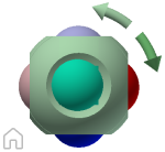
An optional shadow displays below the ViewBowl. It indicates which direction is defined as North for the model.
Note: The model ground plane position is related to the ViewBowl. Redefining the ViewBowl can affect the position of the ground plane.
As view changes occur, the ViewBowl repositions to provide visual feedback about the current viewpoint of the model.
To control the view of the model, you can:
- Drag or click the ViewBowl.
- Switch to one of the available preset views.
- Roll the current view.
- Change to the Home view.
When you click the ViewBowl to reorient a model, the model pivots around a point at the center of the object that you last selected.
Appearance of ViewBowl
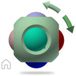
The ViewBowl displays in either the inactive or active state. When inactive, it appears partially transparent by default. When active, it is opaque and can obscure the view of the objects in the current view of the model.
You can control the inactive opacity level of the ViewBowl, and the:
- Size
- Position
- Default orientation
- Shadow(North)
Perspective and Orthographic Views
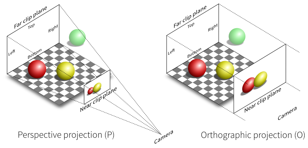
The ViewBowl supports two different view projections:
Perspective projected views are calculated based on the distance from a theoretical camera and target point. The shorter the distance between the camera and the target point, the more distorted the perspective effect appears. Greater distances produce less distorted effects on the model.
Orthographic projected views display all the points of a model projected parallel to the screen.
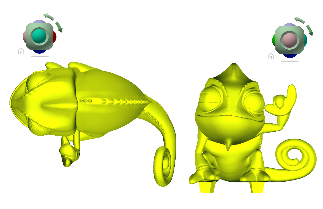
This illustration shows the same model viewed from the same viewing direction, but with different view projections.
Perspective with Ortho Faces. When the view for a model changes, the view updates. It uses the last projection mode, unless the current projection mode set for the ViewBowl is Perspective with Ortho Faces. In that case, all views display in perspective projection, unless you view the model from one of the face views: top, bottom, front, back, left, or right
Lock to Current Selection Option
On the ViewBowl menu, Lock to Current Selection locks the ViewBowl to one or a set of selected objects. It defines the center of the current view, and the distance from center for the view, based on the selected objects.
When Lock to Current Selection is selected:
- Selecting and deselecting objects does not affect the center or distance from the center of the view when a view orientation change occurs with the ViewBowl.
- Overrides Zoom to extents. Zoom to extents does not occur, regardless of the ViewBowl settings.
Display or Hide ViewBowl
- On the ribbon View tab, Windows panel, User Interface drop-down menu, click, or clear ViewBowl.
When cleared, the ViewBowl is available on the Navigation Bar.
Control Appearance of ViewBowl
- Right-click the ViewBowl, and click Options.
- In the ViewBowl Options dialog box, under Display, select from the list:
- On-screen Position
- ViewBowl Size
- Inactive Opacity
- Select from the corresponding drop-down list of options.
- Click OK
Control Appearance of ViewBowl
- Right-click the ViewBowl, and click Options.
- In the ViewBowl Options dialog box, under Display, select from the list:
- On-screen Position
- ViewBowl Size
- Inactive Opacity
- Select from the corresponding drop-down list of options.
- Click OK.
Set View Projection Mode
- Right-click the ViewBowl, and click one of the following options:
- Orthographic
- Perspective
- Perspective with Ortho Faces
Lock the View to One or a Set of Selected Objects.
- Right-click the ViewBowl and click Lock to Current Selection.
If selected when a view orientation change occurs, the ViewBowl uses the selected objects to calculate the center of the view. Then it zooms to the extents of the selected objects. When cleared, the ViewBowl uses the selected objects to calculate the center of the view, and zooms to the extents of the model.
Clear the Lock on a View
- On the ViewBowl menu, clear Lock to Current Selection.
- Click the Lock to Current Selection button (next to the Home view button)
or
ViewBowl Menu Reference
Note: The model ground plane position is related to the ViewBowl. Redefining the ViewBowl can affect the position of the ground plane.
Access
Right-click the Home icon, or the main area of the ViewBowl.
Click the context menu button located near the ViewBowl.
Ribbon: View tab > Windows pane > User Interface > ViewBowl On the drop-down menu, select, or clear ViewBowl to turn on or off the display.
ViewBowl remains available on the Navigation bar.
Go Home
Restores the view you save as the Home view of the model.
Orthographic
Switches the current view to a display mode where all points of a model are projected along parallel lines to the screen.
Perspective
Switches the current view to a display mode where a model is displayed in three-point perspective. Similar to the way the human eye perceives objects in the real world.
Perspective with Ortho Faces
Switches to display the model in orthographic projection when one of the faces of the ViewBowl is active. Not available if the current view aligns with a face view defined on the ViewBowl.
Lock to Current Selection
Locks the view to one or a set of selected objects. Defines the center of the current view and the distance from center for the view, based on the selected objects. Remains locked until cleared.
Note: If you click Home on the ViewBowl, the view returns to the Home view, even if Lock to Current Selection is selected.Set current view as Home
Defines the current view as the default view
Fixed DistanceSets a Home view that defines both the direction of the view and the extent of the model that fills the view. Fit to ViewSets a Home view that defines the direction of the view, with the extent always ‘view all’. The initial Home view of Legacy documents is set to Fit to View. Set current view as Sets the ViewBowl orientation relative to the model. Aligns the current view to look at the TOP or FRONT of the model, then sets the current view with the appropriate selection.
The ViewBowl Bottom view determines the orientation of the model ground plane. Redefining the ViewBowl affects the model ground plane, ground shadows, and ground reflections.
Reset Front
Resets the front view to the default setting.
The front view that is defined in the top-level assembly file prevails as the front view when you edit a part in an assembly file.
This orientation is assigned to migrated legacy files.
Options
Opens the ViewBowl Options dialog box.
Help Topics
Launches the online Help system, and displays the topic on the ViewBowl.
ViewBowl Options Reference
Access
On the Tools tab Options panel Application Options, click the Display tab, and then click ViewBowl.
Right-click the ViewBowl, and select Options.
Options
Show ViewBowl on window create
When selected, displays the ViewBowl in the graphics window by default.
All 3D Views
Displays the ViewBowl in all 3D views.
Only in Current View
Limits the default display of the ViewBowl to the Current view.
On Screen Position
Places the ViewBowl in any corner of the screen. In the On-screen Position combo box control, select Top Right, Bottom Right, Top Left, or Bottom Left.
ViewBowl Size
Sets the ViewBowl size to Tiny, Small, Normal, or Large.
Inactive Opacity
When the cursor is near the ViewBowl, the cube and all the additional controls display fully opaque. When the cursor is distant from the ViewBowl, the additional controls (except the Home button) do not display. You can display the ViewBowl and the Home button at reduced opacity. Specifies the opacity display when the cursor is distant (inactive) from the ViewBowl.
When you drag the ViewBowl
Snap to the closest view When you drag it, the ViewBowl and the scene rotate like an arcball. If Snap to closest view is selected, the viewpoint snaps to the fixed view that it is angularly close to.
When you click ViewBowl
Fit-to-View on view change
If selected, clicking the ViewBowl rotates around the center of the scene and zooms out to fit the scene into the viewport. When you drag the ViewBowl, the view changes to look at the scene center before the drag (but does not zoom). During the drag, it uses that center as the pivot point.
Note: When navigating about 3D scenes that contain vast amounts of geometry, the application frame rate can drop significantly. It is difficult for the system to animate a viewpoint transition smoothly.
Keep model upright
When you click edges, corners, or faces of the ViewBowl, turns the viewpoint to avoid upside-down orientations of the scene.
Default ViewBowl Orientation
Set preferences for the default orientation of the ViewBowl. When a new part or assembly is created from a template, it inherits the orientation from the base template.
Front View Plane
Sets the model-space plane to the expected alignment of the front plane of the ViewBowl.
Top View Plane
Sets the model-space plane to the expected alignment of the top plane of the ViewBowl.
Document Settings
Set preferences for the display of the Compass. By default, the display is off.
Show Compass below ViewBowl
Sets the preference for the display of the Compass.
Angle of North
Sets the angle between the ViewBowl FRONT face and the Compass direction North.
About Reorienting the View
ViewBowl is used to reorient the current view of a model.You can reorient the view of a model with the ViewBowl tool by clicking pre-defined areas to set a preset view current, click and drag to freely change the view angle of the model, and define and restore the Home view.
Reorient the Current View
The ViewBowl tool provides twenty-six defined parts to click and change the current view of a model. The twenty-six defined parts are categorized into three groups: corner, edge, and face. Of the twenty-six defined parts, six of the parts represent standard orthogonal views of a model: top, bottom, front, back, left, and right. Orthogonal views are set by clicking one of the faces on the ViewBowl tool.
Note: When the cursor is over one of the clickable areas of the ViewBowl tool, the cursor changes to an arrow with a small cube to indicate that it is over the ViewBowl tool. A tooltip is also displayed. The tooltip describes the action that you can perform based on the location of the cursor over the ViewBowl tool.You use the other twenty defined parts to access angled views of a model. Clicking one of the corners on the ViewBowl tool reorients the current view of the model to a three-quarter view, based on a viewpoint defined by three sides of the model. Clicking one of the edges reorients the view of the model to a half view based on two sides of the model.
.
You can also click and drag the ViewBowl tool to reorient the view of a model to a custom view other than one of the twenty-six predefined parts. As you drag, the cursor changes to indicate that you are reorienting the current view of the model. If you drag the ViewBowl tool close to one of the preset orientations and it is set to snap to the closest view, the ViewBowl tool rotates to the closest preset orientation.
The outline of the ViewBowl tool helps you identify the form of orientation it is in: standard or fixed. When the ViewBowl tool is in standard orientation, not orientated to one of the twenty-six predefined parts, its outline is displayed as dashed. The ViewBowl tool is outlined in a solid continuous line when it is constrained to one of the predefined views.
Roll a Face View
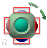
When you view a model from one of the face views, two roll arrow buttons are displayed near the ViewBowl tool. Use the roll arrows to rotate the current view 90 degrees clockwise or counterclockwise around the center of the view.
Switch to an Adjacent Face
When the ViewBowl tool is active while viewing a model from one of the face views, four orthogonal triangles are displayed near the ViewBowl tool. You use these triangles to switch to one of the adjacent face views.
Front View
You can define the Front view of a model to define the direction of the face views on the ViewBowl tool. Along with the Front view, the up direction of a model is also used to define the direction of the face views on the ViewBowl tool.
Note: Front view is a global setting and will be the same for viewpoints.
To Reorient the View
Reorient to a preset or an adjacent face, orbit the model, use animated transitions, roll a face view, examine an object, and moreTo Reorient Current View a Preset Orientation
Click one of the faces, edges, or corners on the ViewBowl tool.
To Reorient to an Adjacent Face
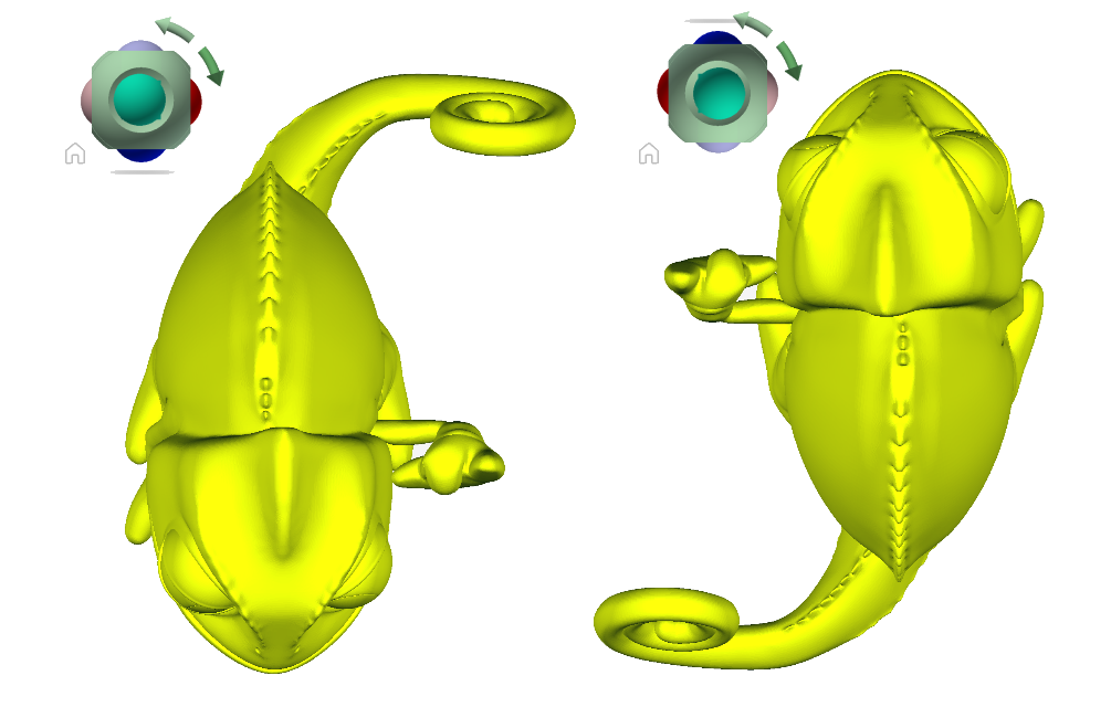
Note: A face view must be current.
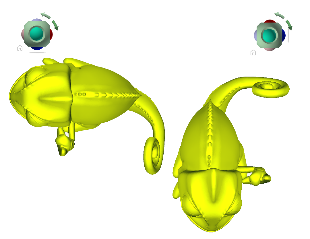
- Also click on one of the hemispheres that appear protruding from the sphere of the ViewBowll.
Each hemispheres switches to one of the adjacent face views, as in this example.
To Orbit the Model
- Click the ViewBowl tool, hold down the left mouse button, and drag in the direction that you want to orbit the model.
With Animated Transitions
- Right-click the ViewBowl tool, and click ViewBowl Options.
- In the Options Editor, the ViewBowl page under the Interface node, select Use Animated Transitions When Switching Views.
When checked, transitions from one view to another appear animated when clicking a predefined area on the ViewBowl tool. - Click OK.
To Roll a Face View
Note: Make sure a face view is displayed.
- Click one of the roll arrows displayed above and to the right of the ViewBowl tool. The left roll arrow rotates the view 90 degrees counterclockwise.
To Examine an Object
- In the model, select one or more objects to define the center point of the view.
- On the ViewBowl, click one of the preset locations, or click and drag the ViewBowl to reorient the view of the model.
The ViewBowl reorients the view of the model based on the center point of the selected objects.
To Automatically Fit Model in View
- Right-click ViewBowl, and click Options.
- In the ViewBowl Options dialog box, under When Clicking on the ViewBowl, click Fit-to-View On View Change.
When selected, you can click a pre-defined area of the ViewBowl to reorient the model, and fit the model to the window. - Click OK
To Define the Front View
- Right-click the ViewBowl, and click Set Current View as Front.
Note: First, orient the view. Use a view tool so that you can see what you consider is the Front of the model, with its Top facing upward. Then, choose Set Current View as Front.
To Restore the Front View
- Right-click the ViewBowl, and click Reset Front.
To Set Home View
- Right-click the ViewBowl, and click Set Current View as Home.
To Reorient Model to Home View
- Right-click the ViewBowl, and click Go Home.
To Apply Saved Home View to Current View
- Right-click Home (
 ) located near the ViewBowl.